Always Read for Knowledge

Friday, 29 April 2011

CCNA LAB Practice - Address Learning Mechanism Of Switch


Address Learning Mechanism

Of

Switch


Objective


This lab demonstrates  address learning mechanism of Switches.

The demonstrations include :

  1. Dynamic Method (Default Method).
  2. Permanent Method.
  3. Restricted Static Method.

i. Dynamic Method

It is the by-default learning method of the switches. The entry remains in the table, if the communication does not exist within the 300 seconds.

Diagram


Procedure

  1. Ping from Host ‘A’ to Host ‘B’.
  2. Verifying the Mac Addresses of the Hosts by the command.
  3. Remove the Dynamic entry of the Hosts

Configuration         

Step 1(A): Ping from Host ‘A’ to Host ‘B’.

D:\>ping 10.0.0.2

Pinging 10.0.0.2 with 32 bytes of data:

Reply from 10.0.0.2: bytes=32 time<10ms TTL=128

Ping statistics for 10.0.0.2:
    Packets: Sent = 4, Received = 4, Lost = 0 (0% loss),
Approximate round trip times in milli-seconds:
    Minimum = 0ms, Maximum =  0ms, Average =  0ms

Step 2: Verifying the Mac Addresses of the Hosts by the command.

1900-SWA#show mac-address-table

Number of permanent addresses : 0
Number of restricted static addresses : 0
Number of dynamic addresses : 2

Address                      Dest Interface       Type         Source Interface List
---------------------------------------------------------------------------------------
0050.DA23.C9DD    Ethernet 0/1      Dynamic                    All
0001.0262.FCC4      Ethernet 0/2      Dynamic                    All

Step 3: Remove the Dynamic Entry of the Hosts.

1900-SWA#clear mac-address-table

ii. Permanent Method

In the permanent method, the Mac-addresses do not age-out. The entry remains in the table either the device attached to the switch or not.

Diagram


Procedure

  1. Define the permanent entry of the both Hosts.
  2. Ping from Host ‘A’ to Host ‘B’.
  3. Verifying the Mac Addresses of the Hosts by the command.
  4. Remove the permanent entry of the Hosts.

Configuration         

Step 1: Define the permanent entry of the both Hosts.

1900-SWA(config)#mac-address-table permanent 0050.DA23.C9DD e0/1
1900-SWA(config)#mac-address-table permanent 0001.0262.FCC4 e0/2

Step 2: Ping from Host ‘A’ to Host ‘B’.

D:\>ping 10.0.0.2

Pinging 10.0.0.2 with 32 bytes of data:

Reply from 10.0.0.2: bytes=32 time<10ms TTL=128

Ping statistics for 10.0.0.2:
    Packets: Sent = 4, Received = 4, Lost = 0 (0% loss),
Approximate round trip times in milli-seconds:
    Minimum = 0ms, Maximum =  0ms, Average =  0ms

Step 3: Verifying the Mac Addresses of the Hosts by the command.

1900-SWA#show mac-address-table

OR

1900-SWA#show mac-address-table permanent

Number of permanent addresses : 2
Number of restricted static addresses : 0
Number of dynamic addresses : 0

Address                  Dest Interface         Type         Source Interface List
------------------------------------------------------------------------------------------
0001.0262.FCC4      Ethernet 0/2      Permanent                    All
0050.DA23.C9DD    Ethernet 0/1      Permanent                    All

Step 4: Remove the permanent entry of the Hosts.

1900-SWA#clear mac-address-table permanent


iii. Restricted Static Method

In the restricted static method, the Mac-addresses do not age-out as well as it define the list that which source interface can talk/communicate with this destination interface.

Diagram


Procedure

  1. Define the restricted static of the both Hosts.
  2. Ping from Host ‘A’ to Host ‘B’.
  3. Verifying the Mac Addresses of the Hosts by the command.
  4. Remove the permanent entry of the Hosts.

Configuration         

Step 1: Define the Restricted Static entry of the both Hosts.

1900-SWA(config)#mac-address-table restricted static 0050.DA23.C9DD e0/1 e0/2
1900-SWA(config)#mac-address-table restricted static 0001.0262.FCC4 e0/2 e0/1

Step 2: Ping from Host ‘A’ to Host ‘B’.

D:\>ping 10.0.0.2

Pinging 10.0.0.2 with 32 bytes of data:

Reply from 10.0.0.2: bytes=32 time<10ms TTL=128

Ping statistics for 10.0.0.2:
    Packets: Sent = 4, Received = 4, Lost = 0 (0% loss),
Approximate round trip times in milli-seconds:
    Minimum = 0ms, Maximum =  0ms, Average =  0ms

Step 3: Verifying the Mac Addresses of the Hosts by the command.

1900-SWA#show mac-address-table

OR

1900-SWA#show mac-address-table restricted static

Number of permanent addresses : 0
Number of restricted static addresses : 2
Number of dynamic addresses : 0

Address                  Dest Interface     Type         Source Interface List
---------------------------------------------------------------------------------------
0001.0262.FCC4      Ethernet 0/2      Static              Et0/1
0050.DA23.C9DD    Ethernet 0/1      Static              Et0/2

Step 4: Remove the Restricted Static entry of the Hosts.

1900-SWA#clear mac-address-table restricted static

CCNA LAB Practice - Accessing Switch through Telnet & Http


Accessing Switch

through

Telnet & Http

 Objective

This lab demonstrates how to access the Switch through the remote ways e.g. through Telnet & Http.

Diagram


Procedure

  1. Set the Privileged Mode Password on Switch.
  2. Give the IP Address of Management VLAN Of Switch.
  3. Verification of connectivity of PC & Switch by ping command.
  4. Telnet to Switch by telnet command on PC.
  5. Open Internet Explorer on PC and Type IP Address of Switch.

Configuration         

Step 1: Set the Privileged/Administrative Mode Password in Clear Text.

1900-SWA(config)#enable password level 15 cisco

Step 2: To give the IP Address of Management VLAN Of 1900-SWA.

1900-SWA(config)#ip address 10.0.0.10 255.0.0.0

Step 3: Verification of connectivity of PC & Switch by ping command.

D:\>ping 10.0.0.10

Pinging 10.0.0.10 with 32 bytes of data:

Reply from 10.0.0.10: bytes=32 time<10ms TTL=128

Ping statistics for 10.0.0.10:
    Packets: Sent = 4, Received = 4, Lost = 0 (0% loss),
Approximate round trip times in milli-seconds:
    Minimum = 0ms, Maximum =  0ms, Average =  0ms

Step 4: Telnet to Switch by telnet command on PC.
                  
C:\>telnet 10.0.0.10


Step 5: Open Internet Explorer on PC and Type IP Address of Switch.

Username: Administrator
Password: (Priviledge Mode Password)


The following Screen wills pop-up.


CCNA LAB Practice - TFTP Server 1


TFTP Server

 Objective

This lab demonstrates how you can backup your configuration as well as upload your configuration to the TFTP Server.

The demonstrations include:

  1. Uploading Configuration to the TFTP Server.
  2. Downloading Configuration from the TFTP Server.

i. Uploading Configuration to the TFTP Server


Diagram


Procedure

  1. Make a TFTP Server to Host ‘A’.
  2. Verification of connectivity of PC & Switch by ping command.
  3. Upload the NVRAM Configuration into TFTP Server.
  4. Verifying the uploaded configuration from the TFTP Server.

Configuration         

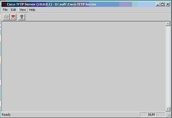
Step 1: Make a TFTP Server to Host ‘A’.


Step 2: Verification of connectivity of PC & Switch by ping command.

1900-SWA#ping 10.0.0.1

Sending 5, 100-byte ICMP Echos to 10.0.0.1, time out is 2 seconds:
!!!!!
Success rate is 100 percent (5/5), round-trip min/avg/max 0/0/0/ ms

Step 3: Upload the NVRAM Configuration into TFTP Server.
                  
1900-SWA#copy nvram tftp://10.0.0.1/configuration.cfg

Configuration upload is successfully completed
1900-SWA#

Step 4: Verifying the uploaded configuration from the TFTP Server.


ii. Downloading Configuration from the TFTP Server


Diagram


Procedure

  1. Make a TFTP Server to Host ‘A’.
  2. Remove the Configuration from the NVRAM.
  3. Give the IP Address to the Switch.
  4. Verification of connectivity of PC & Switch by ping command.
  5. Download the NVRAM Configuration from the TFTP Server.
  6. Verifying the uploaded configuration from the TFTP Server.

Configuration         

Step 1: Make a TFTP Server to Host ‘A’.


Step 2: Remove the Configuration from the NVRAM.

1900-SWA#delete NVRAM

This command resets the switch with factory defaults.  All system
parameters will revert to their default factory settings.  All static
and dynamic addresses will be removed.

Reset system with factory defaults, [Y]es or [N]o?  Yes

Catalyst 1900 Management Console
Copyright (c) Cisco Systems, Inc.  1993-1999
All rights reserved.
Enterprise Edition Software
Ethernet Address:      00-04-DD-4E-81-40

PCA Number:            73-3122-04
PCA Serial Number:     FAB0503D0FV
Model Number:          WS-C1912-A
System Serial Number:  FAB0503W0GW
Power Supply S/N:      PHI044207GX
PCB Serial Number:     FAB0503D0FV,73-3122-04
-------------------------------------------------

1 user(s) now active on Management Console.

        User Interface Menu

     [M] Menus
     [K] Command Line
     [I]   IP Configuration
     [P] Console Password

Enter Selection:  K

      CLI session with the switch is open.
      To end the CLI session, enter [Exit].

>enable
#

Step 3: Give the IP Address to the Switch.

 (config)#ip address 10.0.0.10 255.0.0.0

Step 4: Verification of connectivity of PC & Switch by ping command.

#ping 10.0.0.1
Sending 5, 100-byte ICMP Echos to 10.0.0.1, time out is 2 seconds:
!!!!!
Success rate is 100 percent (5/5), round-trip min/avg/max 0/2/10/ ms

Step 5: Download the NVRAM Configuration from TFTP Server.
                  
#copy tftp://10.0.0.1/configuration.cfg nvram

TFTP successfully downloaded configuration file


Step 6(A): Verifying the uploaded configuration from the TFTP Server.

1900-SWA#show running-config

Building configuration...
Current configuration:
!
hostname "1900-SWA"
!
ip address 10.0.0.10 255.0.0.0
!
enable password level 15 "CISCO"
!
interface Ethernet 0/1
!
!
<Output Omitted>

interface Ethernet 0/12
!
interface Ethernet 0/25
!
interface FastEthernet 0/26
!
interface FastEthernet 0/27
!
line console
end
1900-SWA#

Step 6(B): Verifying the uploaded configuration from the TFTP Server.


CCNA LAB Practice - Port Security


Port Security


Objective


This lab demonstrates the concept of port security mechanism on Switch.

In the port security, we can limit the number of Mac addresses on each port and can define violation method.

Diagram


Procedure

  1. Enable the port Security of the Interfaces.
  2. Define the Max Mac Addresses on the Interfaces.
  3. Verifying the Port Security of the Interfaces by the command.
  4. Define the permanent entry of the both Hosts on the switch.
  5. Ping from Host ‘A’ to Host ‘B’.
  6. Change the interfaces of the Hosts & verifying the Results by the ping command.


Configuration         

Step 1: Enable the port Security of the Interfaces.

1900-SWA(config)#int Ethernet 0/1
1900-SWA(config-if)#port secure
1900-SWA(config)#int Ethernet 0/2
1900-SWA(config-if)#port secure

Step 2: Define the Max Mac Addresses on the Interfaces.

1900-SWA(config)#int Ethernet 0/1
1900-SWA(config-if)#port secure max-mac-count 1
1900-SWA(config)#int Ethernet 0/2
1900-SWA(config-if)#port secure max-mac-count 1

Step 3: Verifying the Port Security of the Interfaces by the command.

1900-SWA#show mac-address-table security

Action upon address violation : Suspend

Interface         Addressing Security       Address Table Size    Clear Address
-------------------------------------------------------------------------------------------
Ethernet 0/1         Enabled                                1                               No
Ethernet 0/2         Enabled                                1                               No
Ethernet 0/3           Disabled                              N/A                            No
Ethernet 0/4           Disabled                              N/A                            No
<Output Omitted>

Step 4: Define the permanent entry of the both Hosts.

1900-SWA(config)#mac-address-table permanent 0050.DA23.C9DD e0/1
1900-SWA(config)#mac-address-table permanent 0001.0262.FCC4 e0/2

Step 5: Ping from Host ‘A’ to Host ‘B’.

D:\>ping 10.0.0.2

Pinging 10.0.0.2 with 32 bytes of data:

Reply from 10.0.0.2: bytes=32 time<10ms TTL=128

Ping statistics for 10.0.0.2:
    Packets: Sent = 4, Received = 4, Lost = 0 (0% loss),
Approximate round trip times in milli-seconds:
    Minimum = 0ms, Maximum =  0ms, Average =  0ms

Step 4: Change the interfaces of the Hosts & verifying the Results by the ping
                 command.

D:\>ping 10.0.0.2

Pinging 10.0.0.2 with 32 bytes of data:

Request timed out.
Request timed out.
Request timed out.
Request timed out.

Ping statistics for 10.0.0.2:
    Packets: Sent = 4, Received = 0, Lost = 4 (100% loss),
Approximate round trip times in milli-seconds:
    Minimum = 0ms, Maximum =  0ms, Average =  0ms

CCNA LAB Practice - I. VLAN Trunking Protocol (VTP)


VLAN

&

VLAN Trunking Protocol

(VTP)

on

1900 Switch


Objective


Understanding the VLAN & VTP operations in switched environment.

The demonstrations include:

  1. To make Vlan’s on 1900 switches & Vlan membership assignments to the ports.
  2. VLAN Trunking Protocol (VTP).

i. VLAN

Diagram


Procedure

  1. Connecting PC’A’ with 1900-SWA switch and verified by Commands.
  2. Display the results that all ports are the members of the Native VLAN (VLAN#1).
  3. Create a VLAN # 2 on 1900-SWA Switch.
  4. Assign a VLAN Member-ship for a Port on 1900-SWA Switch.                 
  5. Verification of VLAN # 2.

Configuration         


Step 1(A): Connecting PC’A’ with 1900-SWA Switch & verified by the Interface
                        Command.

1900-SWA#show interfaces ethernet 0/1

Ethernet 0/1 is Enabled
Hardware is Built-in 10Base-T
Address is 0003.6B33.42C1
MTU 1500 bytes, BW 10000 Kbits
802.1d STP State:  Forwarding     Forward Transitions:  1
Port monitoring: Disabled
Unknown unicast flooding: Enabled
Unregistered multicast flooding: Enabled
Description:
Duplex setting: Full duplex
Back pressure: Disabled
<Output Omitted>

Step 1(B): Connecting PC with 1900 switch and verified by the MAC Address
                        Table Command.

1900-SWA#show mac-address-table

Number of permanent addresses : 0
Number of restricted static addresses : 0
Number of dynamic addresses : 1

Address                      Dest Interface    Type         Source Interface List
-------------------------------------------------------------------------------------
0050.DA23.C9DD    Ethernet 0/1      Dynamic              All

Step 2(A): Display the results that all ports are the members of Native VLAN.

1900-SWA#show vlan

OR


1900-SWA#show vlan 1

VLAN   Name             Status        Ports
------------------------------------------------------------
1            default          Enabled    1-12, AUI, A, B
------------------------------------------------------------

VLAN Type           SAID   MTU    Parent RingNo BridgeNo Stp    Trans1 Trans2
--------------------------------------------------------------------------------------------------
1    Ethernet           100001 1500         0          0             0         Unkn  1002    1003
--------------------------------------------------------------------------------------------------

Step 2(B): Display the results that all ports are the members of Native VLAN.

1900-SWA#show vlan-membership

   Port            VLAN                Membership Type    
   -------        ----------                        -----------------------   
   1                   1                                  Static
   2                   1                                  Static
   3                   1                                  Static
   4                   1                                  Static
   5                   1                                  Static
   6                   1                                  Static
   7                   1                                  Static
   8                   1                                  Static
   9                   1                                  Static
   10                 1                                  Static
   11                 1                                  Static
   12                 1                                  Static
   AUI              1                                  Static
     A                1                                  Static
     B                 1                                  Static


Step 3: Create a VLAN # 2 on 1900-SWA Switch by VLAN command.

1900-SWA(config)#vlan 2 name cttc

Step 4: Assign a Member-ship for Fast Ethernet Port 0/1 on 1900-SWA Switch.                 

1900-SWA(config)#int ethernet 0/1
1900-SWA(config-if)#vlan-membership ?

  dynamic  Set VLAN membership type as dynamic
  static       Set VLAN membership type as static

1900-SWA(config-if)#vlan-membership static ?

  <1-1005>  ISL VLAN index

1900-SWA(config-if)#vlan-membership static 2

Step 5: Verification of VLAN # 2.

1900-SWA#show vlan

OR


1900-SWA#sh vlan 2

VLAN  Name             Status     Ports
--------------------------------------------
2           cttc                 Enabled    1
--------------------------------------------

VLAN Type               SAID    MTU    Parent RingNo BridgeNo Stp      Trans1 Trans2
-------------------------------------------------------------------------------------------------------
2          Ethernet       100002  1500         0          1              1        Unkn       0         0
-------------------------------------------------------------------------------------------------------