Network Address Translation
(NAT)
Objective
Understanding the operation of Network Address Translation. It is used when hosts on LAN do not have globally unique IP Addresses to connect to the internet.
NAT technology enables private IP networks that use non-registered IP addresses to connect to a public network.
The demonstrations include:
- Static NAT
- Dynamic NAT.
- Overload NAT (PAT).
In the Static NAT, we map the 1 Private IP Address to 1 reserved Public IP Address.
Diagram

Procedure
- Configuring & Assigning the IP addresses on the routers R1 & R2.
- Check the routing table on both the routers.
- Enable the routing protocol on both routers so that hosts on the both routers can communicate with each other.
- Check the routing table on both the routers after enabling the routing protocol on both sides.
- Make a web server to the host C & Run the Sniffer.
- Establishes Static NAT Translation between an inside local address and an inside global address.
- Marks the interface as connected to the inside & outside networks.
- Verifying the Standard Static NAT Translation by commands & Sniffer Outputs.
Configuration
Step 1(A): Assigning the IP addresses on the Router R1.
R1(config)#interface serial 0
R1(config-if)#ip address 15.0.0.1 255.0.0.0
R1(config-if)#no shutdown
R1(config-if)#clock rate 64000 (Clock Rate will set only DCE Interface)
R1(config-if)#exit
R1(config)#interface ethernet 0
R1(config-if)#ip address 10.0.0.20 255.0.0.0
R1(config-if)#no shutdown
R1(config-if)#end
Step 1(B): Assigning the IP addresses on the Router R2.
R2(config)#interface serial 0
R2(config-if)#ip address 15.0.0.2 255.0.0.0
R2(config-if)#no shutdown
R2(config-if)#end
R2(config)#interface ethernet 0
R2(config-if)#ip address 20.0.0.2 255.0.0.0
R2(config-if)#no shutdown
R2(config-if)#exit
Step 2(A): Check the Routing table of the Router R1.
RA#sh ip route
C 10.0.0.0/8 is directly connected, Ethernet0
C 15.0.0.0/8 is directly connected, Serial0
Step 2(B): Check the Routing table of the Router R2.
RB#sh ip route
C 20.0.0.0/8 is directly connected, Ethernet0
C 15.0.0.0/8 is directly connected, Serial0
Step 3(A): Enable the RIP protocol on the Router R1.
RA(config)#router rip
RA(config-router)#network 10.0.0.0 (Networks to be advertised)
RA(config-router)#network 15.0.0.0 (Networks to be advertised)
Step 3(B): Enable the RIP protocol on the Router R2.
RB(config)#router rip 10
RB(config-router)#network 20.0.0.0 (Networks to be advertised)
RB(config-router)#network 15.0.0.0 (Networks to be advertised)
Step 4(A): Check the Routing table of the Router R2 after enabling RIP.
RA#sh ip route
R 20.0.0.0/8 [120/1] via 15.0.0.2, 00:04:42 , Serial0
C 10.0.0.0/8 is directly connected, Ethernet0
C 15.0.0.0/8 is directly connected, Serial0
Step 4(B): Check the Routing table of the Router R2 after enabling RIP.
RB#sh ip route
C 20.0.0.0/8 is directly connected, Ethernet0
R 20.0.0.0/8 [120/1] via 15.0.0.1, 00:01:12 , Serial0
C 15.0.0.0/8 is directly connected, Serial0
Step 5(A): Make a Web Server to the Host C & Run the Sniffer.
- Make a Web Page & Save it on Desktop.
- Go to Start Button > All Programs > Administrative Tool > Internet Service Manager
- Right Click on the Computer name & goes to New tab > Web Site.
- Follow the wizard and make the Web Server.
- Run the Sniffer & capturing the www traffic.
Step 6: Establishes Static NAT Translation between an inside local address
and an inside global address.
R1(config)#ip nat inside source static 10.0.0.1 15.0.0.11
R1(config)#ip nat inside source static 10.0.0.2 15.0.0.22
Step 7(A): Marks the interface as connected to the Inside Network.
R1(config)#int Ethernet 0
R1(config-if)#ip nat inside
Step 7(B): Marks the interface as connected to the Outside Network.
R1(config)#int serial 0
R1(config-if)#ip nat inside
Step 8(A): Verifying the Static NAT Translation on Router R1 by translation
table command.
R1#show ip nat translations
Pro Inside global Inside local Outside local Outside global
--- 15.0.0.11 10.0.0.1 --- ---
--- 15.0.0.22 10.0.0.2 --- ---
Step 8(B): Verifying the Static NAT Translation on Router R1 by debug.
R1#debug ip nat
IP NAT debugging is on
When Host ’A’ pings to Host ‘C’:
When Host ’B’ pings to Host ‘C’:
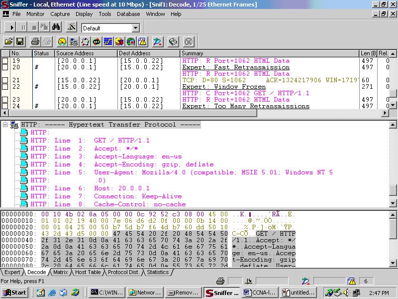
Step 8(C): Verifying the Static NAT Translation by Sniffer Output by accessing
the Web Server from Host ‘A’.

Step 8(D): Verifying the Static NAT Translation by Sniffer Output by accessing
the Web Server from Host ‘B’.
No comments:
Post a Comment