iii. Overload NAT (PAT)
In the Overload NAT, we map the many Private IP Addresses to 1 Public IP Address.
Diagram

Procedure
- Configuring & Assigning the IP addresses on the routers R1 & R2.
- Check the routing table on both the routers.
- Enable the routing protocol on both routers so that hosts on the both routers can communicate with each other.
- Check the routing table on both the routers after enabling the routing protocol on both sides.
- Make a web server to the host C & Run the Sniffer.
- Defines a pool of global addresses to be allocated as needed.
- Defines a standard IP access list permitting those inside local addresses that are to be translated.
- Establishes dynamic source translation, specifying the access list defined in the prior step.
- Marks the interface as connected to the inside & outside networks.
- Verifying the Standard Dynamic translation by commands & Sniffer Outputs.
Configuration
Step 1(A): Assigning the IP addresses on the Router R1.
R1(config)#interface serial 0
R1(config-if)#ip address 15.0.0.1 255.0.0.0
R1(config-if)#no shutdown
R1(config-if)#clock rate 64000 (Clock Rate will set only DCE Interface)
R1(config-if)#exit
R1(config)#interface ethernet 0
R1(config-if)#ip address 10.0.0.20 255.0.0.0
R1(config-if)#no shutdown
R1(config-if)#end
Step 1(B): Assigning the IP addresses on the Router R2.
R2(config)#interface serial 0
R2(config-if)#ip address 15.0.0.2 255.0.0.0
R2(config-if)#no shutdown
R2(config-if)#end
R2(config)#interface ethernet 0
R2(config-if)#ip address 20.0.0.2 255.0.0.0
R2(config-if)#no shutdown
R2(config-if)#exit
Step 2(A): Check the Routing table of the Router R1.
RA#sh ip route
C 10.0.0.0/8 is directly connected, Ethernet0
C 15.0.0.0/8 is directly connected, Serial0
Step 2(B): Check the Routing table of the Router R2.
RB#sh ip route
C 20.0.0.0/8 is directly connected, Ethernet0
C 15.0.0.0/8 is directly connected, Serial0
Step 3(A): Enable the RIP protocol on the Router R1.
RA(config)#router rip
RA(config-router)#network 10.0.0.0 (Networks to be advertised)
RA(config-router)#network 15.0.0.0 (Networks to be advertised)
Step 3(B): Enable the RIP protocol on the Router R2.
RB(config)#router rip 10
RB(config-router)#network 20.0.0.0 (Networks to be advertised)
RB(config-router)#network 15.0.0.0 (Networks to be advertised)
Step 4(A): Check the Routing table of the Router R2 after enabling RIP.
RA#sh ip route
R 20.0.0.0/8 [120/1] via 15.0.0.2, 00:04:42 , Serial0
C 10.0.0.0/8 is directly connected, Ethernet0
C 15.0.0.0/8 is directly connected, Serial0
Step 4(B): Check the Routing table of the Router R2 after enabling RIP.
RB#sh ip route
C 20.0.0.0/8 is directly connected, Ethernet0
R 20.0.0.0/8 [120/1] via 15.0.0.1, 00:01:12 , Serial0
C 15.0.0.0/8 is directly connected, Serial0
Step 5(A): Make a Web Server to the Host C & Run the Sniffer.
- Make a Web Page & Save it on Desktop.
- Go to Start Button > All Programs > Administrative Tool > Internet Service Manager
- Right Click on the Computer name & goes to New tab > Web Site.
- Follow the wizard and make the Web Server.
- Run the Sniffer & capturing the www traffic.
Step 6: Defines a pool of global addresses to be allocated as needed.
R1(config)#ip nat pool cttc 15.0.0.200 15.0.0.200 prefix-length 8
Step 7: Defines a standard IP access list permitting those inside local addresses
that are to be translated.
R1(config)#access-list 1 permit 10.0.0.0 0.255.255.255
Step 8: Establishes dynamic source translation, specifying the access list defined
in the prior step.
R1(config)#ip nat inside source list 1 pool cttc overload
Step 9(A): Marks the interface as connected to the Inside Network.
R1(config)#int Ethernet 0
R1(config-if)#ip nat inside
Step 9(B): Marks the interface as connected to the Outside Network.
R1(config)#int serial 0
R1(config-if)#ip nat inside
Step 10(A): Verifying the Overload NAT Translation on Router R1 by
debugging command..
R1#debug ip nat
IP NAT debugging is on
When Host ’A’ pings to Host ‘C’:
When Host ’B’ pings to Host ‘C’:
Step 10(B): Verifying the Dynamic NAT Translation on Router R1 by
translation table.
R1#show ip nat translations
Pro Inside global Inside local Outside local Outside global
tcp 15.0.0.200:1041 10.0.0.1:1041 20.0.0.1:80 20.0.0.1:80
tcp 15.0.0.200:1042 10.0.0.2:1042 20.0.0.1:80 20.0.0.1:80
Step 10(C): Verifying the Dynamic NAT Translation by Sniffer Output by
accessing the Web Server from Host ‘A’.
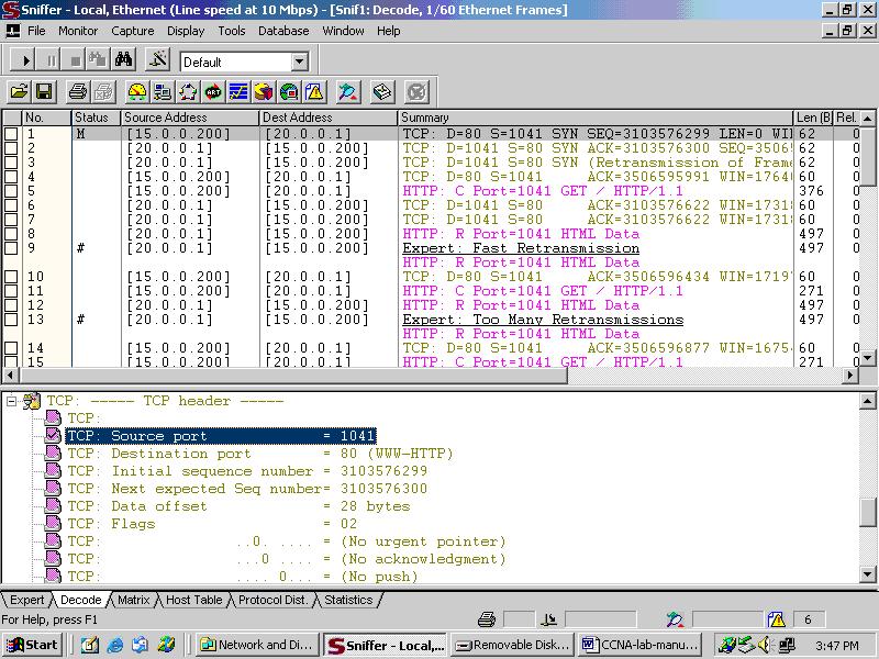
Step 10(D): Verifying the Dynamic NAT Translation by Sniffer Output by
accessing the Web Server from Host ‘B’.

No comments:
Post a Comment